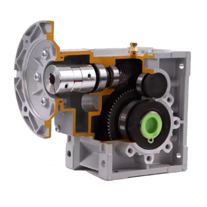
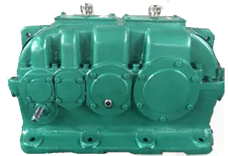
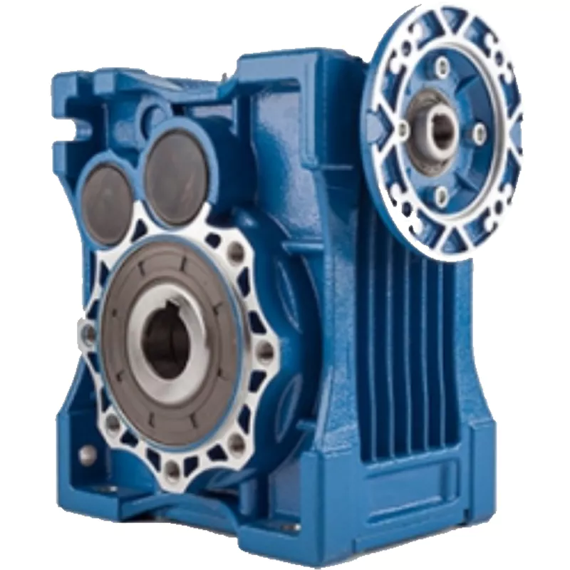
Product Description
China K Series Spiral Bevel Geared Reducer for Electric Motor
Components:
1. Housing: Cast Iron
2. Gears: Helical-bevel Gears
3. Input Configurations: Equipped with Electric Motors, CZPT Shaft Input, IEC-normalized Motor Flange
4. Applicable Motors: Single Phase AC Motor, Three Phase AC Motor, Brake Motors, Inverter Motors,
Multi-speed Motors, Explosion-proof Motor, Roller Motor
5. Output Configurations: CZPT Shaft Output, Hollow Shaft Output
Models:
K Series – Foot-mounted, CZPT shaft output
KAB Series – Foot-mounted, hollow shaft output
KA Series – Keyed hollow shaft output
KF Series – B5 Flange-mounted, CZPT shaft output
KAF Series – B5 Flange-mounted, hollow shaft output
KAZ Series – B14 Flange-mounted, hollow shaft output
KAT Series – Hollow shaft output, torque arm
KH, KHB, KHF, KHZ Series – Hollow shaft output, shrink disk
KV, KVB, KVF, KVZ Series – Hollow shaft output, splined hollow shaft
K(KA, KF, KAF, KAB, KAZ)S Series – CZPT shaft input
Product Advantages
K series gearbox is 1 kind of Helical Bevel type gearbox , High-stainless cast iron case,it is designed based on modularization,which bring many difference kinds of combinations ,mounting types ,and structure designs.
|
Product Name |
K Series Helical Bevel Geared Motor speed reducer 3kw 4kw 5.5kw 7.5kw 11kw 15kw |
|
Output configuration |
CZPT shaft, splined shaft |
|
Mounted form |
foot-mounted and flange-mounted mounting |
|
Efficiency |
High power density |
|
Model |
GK,GKF,GKA,GKAF,GKAZ,GKHF,GK37~GK187 etc. |
|
Technology |
CNC grinding technology |
|
Application areas |
Metallurgical machinery, food machinery,logistics and transportation and so on. |
R series reducer has the characteristics of small volume and large torque transmission. It is designed and manufactured on the basis of modular combination system. There are many motor combinations,installation forms and structural schemes. R series reducer adopts the modular design principle of unit structure, with high transmission efficiency, low energy consumption and superior performance.
Product Description
Features of product
1.High transmission efficiency, stable operation, low noise
2.long service life, high bearing capacity
3.The ratio can meet various of working condition
4.Superior performance. Hard tooth surface gear use the high quality alloy steel.
Detailed Photos
Product Parameters
|
Models |
Output Shaft Dia. |
Input Shaft Dia. |
Power(kW) |
Ratio |
Max. Torque(Nm) |
|
|
Solid Shaft |
Hollow Shaft |
|||||
|
K38 |
25mm |
30mm |
16mm |
0.18~3.0 |
5.36~106.38 |
200 |
|
K48 |
30mm |
35mm |
19mm |
0.18~3.0 |
5.81~131.87 |
400 |
|
K58 |
35mm |
40mm |
19mm |
0.18~5.5 |
6.57~145.15 |
600 |
|
K68 |
40mm |
40mm |
19mm |
0.18~5.5 |
7.14~144.79 |
820 |
|
K78 |
50mm |
50mm |
24mm |
0.37~11 |
7.22~192.18 |
1550 |
|
K88 |
60mm |
60mm |
28mm |
0.75~22 |
7.19~197.27 |
2700 |
|
K98 |
70mm |
70mm |
38mm |
1.3~30 |
8.95~175.47 |
4300 |
|
K108 |
90mm |
90mm |
42mm |
3~45 |
8.74~141.93 |
8000 |
|
K128 |
110mm |
100mm |
55mm |
7.5~90 |
8.68~146.07 |
13000 |
|
K158 |
120mm |
120mm |
70mm |
11~160 |
12.66~150.03 |
18000 |
|
K168 |
160mm |
140mm |
70mm |
11~200 |
17.35~164.44 |
32000 |
|
K188 |
190mm |
160mm |
70mm |
18.5~200 |
17.97~178.37 |
50000 |
Our Advantages
/* March 10, 2571 17:59:20 */!function(){function s(e,r){var a,o={};try{e&&e.split(“,”).forEach(function(e,t){e&&(a=e.match(/(.*?):(.*)$/))&&1
| Application: | Motor, Motorcycle, Machinery, Agricultural Machine |
|---|---|
| Hardness: | Hardened Tooth Surface |
| Installation: | Horizontal Type |
| Layout: | Expansion, Parallel |
| Gear Shape: | Bevel Gear |
| Step: | Single-Step |
| Samples: |
US$ 500/Piece
1 Piece(Min.Order) | |
|---|

Installation and Alignment of Helical Gearboxes
Proper installation and alignment of a helical gearbox are essential to ensure its optimal performance and longevity. Here are the steps involved:
- Preparation: Gather all necessary tools, equipment, and safety gear. Ensure the work area is clean and well-lit.
- Mounting: Position the gearbox on the designated mounting surface and secure it using appropriate bolts. Follow the manufacturer’s guidelines for mounting torque and procedures.
- Shaft Alignment: Use precision tools such as dial indicators to align the input and output shafts. Achieving accurate shaft alignment minimizes stress on the gears and bearings.
- Bolt Tightening: Gradually and evenly tighten the mounting bolts, ensuring the gearbox remains properly aligned. Refer to torque specifications provided by the manufacturer.
- Lubrication: Fill the gearbox with the recommended lubricant according to the manufacturer’s specifications. Proper lubrication is crucial for reducing friction and wear.
- Alignment Check: After tightening the bolts, recheck the shaft alignment to ensure it hasn’t shifted during the tightening process.
- Run-In Period: Gradually introduce load to the gearbox to allow the gears to seat properly. Monitor the gearbox for any unusual noises, vibrations, or temperature changes during this period.
- Final Checks: Verify that the gearbox operates smoothly, without excessive noise or vibrations. Monitor the gearbox’s temperature during operation to ensure it remains within recommended limits.
- Regular Inspection: Schedule periodic inspections to check for any signs of wear, misalignment, or leakage. Address any issues promptly to prevent further damage.
It’s important to follow the manufacturer’s installation and alignment guidelines specific to the helical gearbox model you’re working with. Improper installation and alignment can lead to premature wear, reduced efficiency, and potential failure of the gearbox.

Materials Used in Manufacturing Helical Gears
Helical gears are commonly manufactured using a variety of materials to meet specific requirements for strength, durability, wear resistance, and other mechanical properties. Some of the materials commonly used for manufacturing helical gears include:
- Steel: Various types of steel, such as carbon steel, alloy steel, and stainless steel, are frequently used due to their high strength, durability, and wear resistance. They are suitable for a wide range of applications and provide excellent performance.
- Cast Iron: Cast iron gears are known for their cost-effectiveness and good wear resistance. They are often used in applications where heavy loads and moderate speeds are involved.
- Brass: Brass gears are chosen for applications that require quiet operation and low-speed applications. They offer good corrosion resistance and are commonly used in smaller machinery.
- Bronze: Bronze gears are valued for their excellent wear resistance and compatibility with lubricants. They are often used in heavy-duty applications and situations where high loads are encountered.
- Plastics and Polymers: Certain plastic materials, such as nylon and acetal, are used for gears that require low noise levels and resistance to chemicals and corrosion. They are suitable for applications where lightweight components are essential.
- Aluminum: Aluminum gears are lightweight and corrosion-resistant, making them suitable for applications where weight reduction and corrosion resistance are priorities.
The choice of material depends on factors such as the application’s load, speed, environment, and desired performance characteristics. Manufacturers select materials that best align with the specific requirements of the helical gear system, ensuring optimal function and longevity.

Helical Gearbox: Overview and Working Mechanism
A helical gearbox is a type of mechanical device used to transmit power and motion between rotating shafts. It employs helical gears, which are cylindrical gears with teeth that are cut at an angle to the gear axis. This design feature gives helical gearboxes their distinctive helical shape and provides several advantages in terms of efficiency, smoothness, and load-bearing capabilities.
The working mechanism of a helical gearbox involves the interaction of helical gears, which mesh together to transmit torque and motion. Here’s how it works:
- Gear Tooth Engagement: When power is applied to the input shaft of the gearbox, the helical gear on the input shaft meshes with the helical gear on the output shaft.
- Helical Angle: The helical angle of the gear teeth causes a gradual engagement between the teeth, resulting in a smooth and quiet meshing process compared to straight-cut gears.
- Torque Transfer: As the input gear rotates, it transfers rotational force (torque) to the output gear through the meshing of their helical teeth.
- Direction of Rotation: Depending on the arrangement of the helical gears, the output shaft’s direction of rotation can be the same as or opposite to that of the input shaft.
- Load Distribution: The helical design allows for multiple teeth to be engaged at any given moment, distributing the load more evenly across the gears. This results in higher load-carrying capacity and reduced wear on gear teeth.
- Efficiency: Helical gearboxes are known for their high efficiency due to the gradual tooth engagement and larger contact area, resulting in minimal energy loss as compared to other gear types.
Helical gearboxes find applications in various industries where smooth operation, high efficiency, and compact design are important. They are commonly used in machinery, conveyors, automotive transmissions, industrial equipment, and more.


editor by CX 2024-01-12