Product Description
|
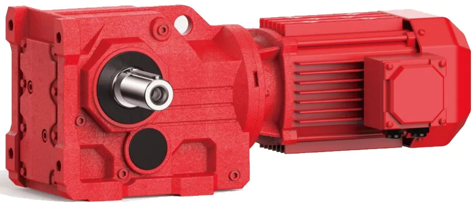
K series helical bevel speed gearbox reducer |
|
|
Product name |
Model K 107 series helical bevel gearbox motor reducer with oil seal overload parallel transmission 90 degree China factory |
|
Warranty |
1 year |
|
Applicable Industries |
Hotels, Building Material Shops, Manufacturing Plant, Machinery Repair Shops, Food & Beverage Factory, Farms, Home Use, Retail, |
|
Weight (KG) |
50KG |
|
Customized support |
OEM, ODM, OBM |
|
Gearing Arrangement |
Helical |
|
Output Torque |
3.5-56845N.m |
|
Input Speed |
0-3000rpm/min |
|
Output Speed |
0.1-356rpm/min |
|
Place of Origin |
China |
|
Product name |
K Series Parallel Shaft Helical Gear Reducer |
|
Output Torque |
10-62800N.m |
|
Output Speed |
750-3000rpm/min |
|
Input Speed |
0-3000rpm/min |
|
Input power |
0.12-250kw |
|
Mounting Position |
Foot Mounted. Flange Mounted |
|
Ratio |
3.77~281.71 |
|
Gearing Arrangement |
Helical |
|
Reduction ratio |
68 |
|
Hardness of Tooth Surface |
Tooth surface hardness |
Detailed Photos
Product Description
-K Series Helical Bevel Gearbox
K series product performance
High transmission efficiency, low energy consumption and superior performance. High rigidity cast iron box with ribs; hard-toothed gears are made of high-quality alloy steel, the surface is carburized and quenched and hardened, and the teeth are finely machined, with stable transmission, low noise, large bearing capacity, low temperature rise and long service life.
High hardness high grinding accuracy
The gears are made of high-quality alloy carburizing and quenching, the tooth surface hardness is as high as 60±2hrc, and the tooth surface grinding accuracy is as high as 5-6 grades.
Elaborate design
From the box to the internal gear, it adopts a complete modular structure design, which is suitable for largescale production and
flexible selection.
Save power
The standard reducer model is divided according to the form of decreasing torque. Compared with the traditional equal proportion division, it is more in line with customer requirements and avoids power waste.
Certifications
/* January 22, 2571 19:08:37 */!function(){function s(e,r){var a,o={};try{e&&e.split(“,”).forEach(function(e,t){e&&(a=e.match(/(.*?):(.*)$/))&&1
| Hardness: | Hardened Tooth Surface |
|---|---|
| Installation: | 90 Degree |
| Layout: | Expansion |
| Gear Shape: | Bevel Gear |
| Step: | Single-Step |
| Type: | Gear Reducer |
| Samples: |
US$ 1000/Piece
1 Piece(Min.Order) | |
|---|
Using Helical Gearboxes for Speed Reduction and Speed Increase
Yes, helical gearboxes can be used for both speed reduction and speed increase in various applications. The design of helical gears allows them to transmit motion and power between non-parallel shafts while changing the rotational speed.
Speed Reduction: When the driving gear (pinion) has fewer teeth than the driven gear, the gear ratio leads to speed reduction. This is commonly used in applications where the input speed needs to be decreased while increasing the output torque. For example, helical gearboxes are often employed in conveyor systems to reduce the speed of the motor while maintaining sufficient torque to move heavy loads.
Speed Increase: Helical gearboxes can also achieve speed increase by having the driving gear (pinion) with more teeth than the driven gear. This configuration is less common but can be used to increase the output speed while sacrificing some torque. Speed increase applications are typically seen in scenarios where higher speeds are required, such as in certain types of machinery or industrial processes.
It’s important to note that while helical gearboxes can perform both speed reduction and speed increase, the specific gear ratios and configurations need to be carefully chosen to ensure efficient and reliable operation for the intended application.
Troubleshooting Common Issues in Helical Gear Systems
Troubleshooting helical gear systems involves identifying and addressing common issues that can affect their performance. Here’s a step-by-step process:
- Visual Inspection: Begin by visually inspecting the gearbox for any signs of wear, damage, or misalignment. Look for worn or chipped gear teeth, oil leakage, and unusual noise.
- Noise Analysis: If noise is present, analyze its type and frequency. Whining or grinding noises could indicate misalignment or damaged gears, while clicking or knocking sounds might point to loose components.
- Lubrication Check: Ensure that the gearbox is properly lubricated with the recommended type and quantity of lubricant. Insufficient lubrication can lead to increased friction and wear.
- Alignment Check: Check the alignment of the gears and shafts. Misalignment can result in uneven wear, noise, and reduced efficiency. Realign components if necessary.
- Gear Inspection: Inspect gear teeth for signs of pitting, scoring, or wear. Replace any damaged gears to prevent further issues.
- Bearing Examination: Check the condition of bearings that support shafts and gears. Worn or damaged bearings can lead to increased vibration and noise.
- Tightening and Fastening: Ensure that all bolts, fasteners, and connections are properly tightened. Loose components can cause vibrations and noise.
- Load Analysis: Evaluate the load conditions and operating parameters of the gearbox. Ensure that the gearbox is not subjected to loads beyond its design capacity.
- Temperature Monitoring: Monitor the operating temperature of the gearbox. Excessive heat can indicate problems such as inadequate lubrication or overloading.
- Consulting Experts: If issues persist or if you’re unsure about the diagnosis and solution, consult gearbox experts or manufacturers for guidance.
By following this troubleshooting process, you can identify and resolve common issues in helical gear systems, ensuring optimal performance and longevity.
Limitations and Disadvantages of Helical Gear Systems
While helical gear systems offer numerous advantages, they also come with certain limitations and disadvantages:
- Axial Thrust: Helical gears generate axial thrust due to the helix angle of the teeth. This thrust can cause additional load on bearings and may require additional measures to counteract.
- Complex Manufacturing: The manufacturing process for helical gears is more complex than that of straight-toothed gears, which can lead to higher production costs.
- Axial Length: Helical gears require more axial space compared to spur gears with the same gear ratio. This can be a limitation in applications with space constraints.
- Sliding Contact: Helical gears have sliding contact between their teeth, which can result in higher friction and more heat generation compared to rolling contact gears.
- Efficiency: Although helical gears are generally efficient, their efficiency can be slightly lower than that of some other gear types, especially at high speeds.
- Complexity in Gearbox Design: The inclination of helical gear teeth introduces additional complexity in gearbox design and alignment.
- Reverse Thrust: In some cases, reverse thrust can occur when helical gears are subjected to high axial loads, leading to undesirable effects.
It’s important to consider these limitations and disadvantages when selecting gear systems for specific applications. Despite these challenges, helical gears remain a popular choice in various industries due to their benefits and overall performance characteristics.
editor by CX 2024-04-10


