Product Description
Helical Gear Motor (R Type)
|
Input Configurations |
Direct motor coupled |
|
with IEC B5/B14 motor flange |
|
|
with IEC B5/B14 motor mounted |
|
|
with CZPT input shaft |
|
|
Output Configurations |
CZPT output shaft |
|
CZPT output shaft with flange |
|
|
Variants of Helical Gear Unit Series RX / R / RF |
CZPT or 2/3 Stage |
|
Foot- or flange-mounted |
|
|
Foot- and flange-mounted |
|
|
Flange-mounted with extended bearing housing |
Main Feature
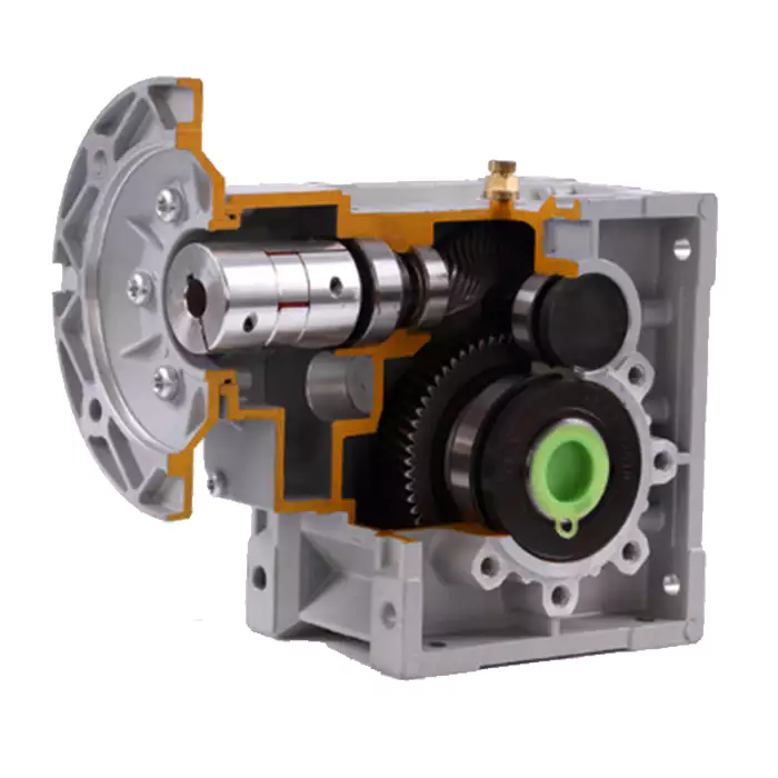
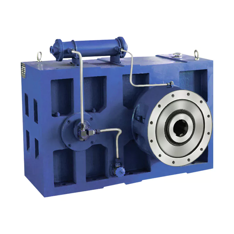
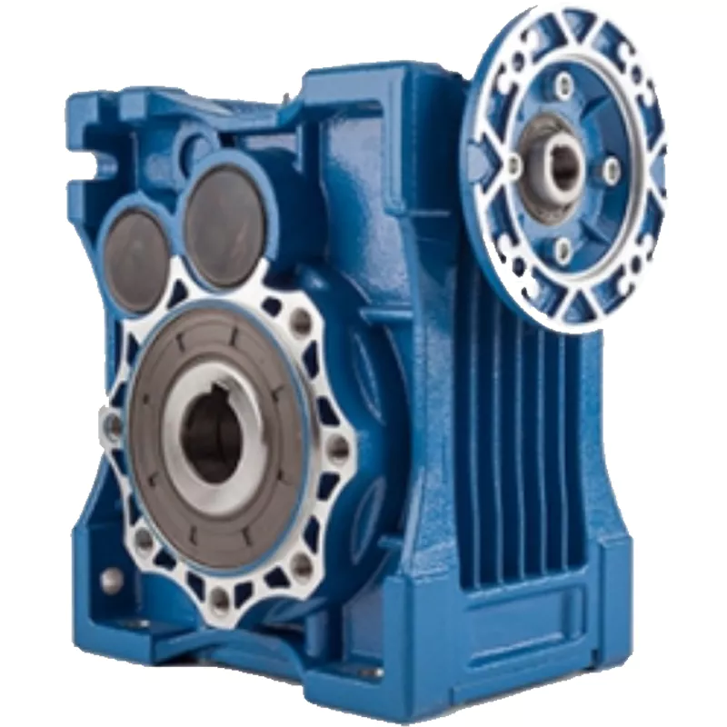
R type gear reducer is an ideal choice for high output speeds or low weight. Always with a high level of efficiency, our helical gear units offer an optimum ratio between output torque and installation space. This means: a helical gear unit almost always fits your application.
Specification
|
Model |
CZPT Output Shaft Dia./Length mm |
Horizontal Center Height mm |
External Flange Dia. mm |
Power (kw) |
Ratio (i) |
Nominal Torque (Nm) |
|
R/RF37 |
ф25/50 |
90 |
120 |
0.12-0.75 |
5-136 |
150 |
|
R/RF47 |
ф30/60 |
115 |
160 |
0.25-2.2 |
5-173 |
300 |
|
R/RF57 |
ф35/70 |
115 |
200 |
1.18-5.5 |
5-173 |
400 |
|
R/RF67 |
ф35/70 |
130 |
200 |
0.37-7.5 |
5-170 |
500 |
|
R/RF77 |
ф40/80 |
140 |
250 |
0.55-11.0 |
5-192 |
750 |
|
R/RF87 |
ф50/100 |
180 |
300 |
0.75-18.5 |
5-192 |
1250 |
|
R/RF97 |
ф60/120 |
225 |
350 |
1.50-30.0 |
5-197 |
2400 |
|
R/RF107 |
ф70/140 |
250 |
350 |
2.20-45.0 |
5-197 |
3600 |
|
R/RF137 |
ф90/170 |
315 |
450 |
4.00-45.00 |
5-197 |
6600 |
|
R/RF147 |
ф110/210 |
355 |
450 |
7.50-90.00 |
5-195 |
10700 |
|
R/RF167 |
ф120/210 |
425 |
550 |
11.00-132.00 |
5-186 |
14800 |
Company Profile
Packing
Scenarioes
FAQ
Q1: I want to buy your products, how can I pay?
A: You can pay via T/T(30%+70%), L/C ,D/P etc.
Q2: How can you guarantee the quality?
A: One year’s warranty against B/L date. If you meet with quality problem, please send us pictures or video to check, we promise to send spare parts or new products to replace. Our guarantee not include inappropriate operation or wrong specification selection.
Q3: How we select models and specifications?
A: You can email us the series code (for example: RC series helical gearbox) as well as requirement details, such as motor power,output speed or ratio, service factor or your application…as much data as possible. If you can supply some pictures or drawings,it is nice.
Q4: If we don’t find what we want on your website, what should we do?
A: We offer 3 options:
1, You can email us the pictures, drawings or descriptions details. We will try to design your products on the basis of our
standard models.
2, Our R&D department is professional for OEM/ODM products by drawing/samples, you can send us samples, we do customized design for your bulk purchasing.
3, We can develop new products if they have good market. We have already developed many items for special using successful, such as special gearbox for agitator, cement conveyor, shoes machines and so on.
Q5: Can we buy 1 pc of each item for quality testing?
A: Yes, we are glad to accept trial order for quality testing.
Q6: How about your product delivery time?
A: Normally for 20’container, it takes 25-30 workdays for RV series worm gearbox, 35-40 workdays for helical gearmotors.
/* January 22, 2571 19:08:37 */!function(){function s(e,r){var a,o={};try{e&&e.split(“,”).forEach(function(e,t){e&&(a=e.match(/(.*?):(.*)$/))&&1
| Application: | Motor, Machinery, Agricultural Machinery |
|---|---|
| Hardness: | Hardened Tooth Surface |
| Installation: | Foot/Flange Mounted |
| Layout: | Coaxial |
| Gear Shape: | Cylindrical Gear |
| Step: | Single-Step |
| Customization: |
Available
| Customized Request |
|---|
Installation and Alignment of Helical Gearboxes
Proper installation and alignment of a helical gearbox are essential to ensure its optimal performance and longevity. Here are the steps involved:
- Preparation: Gather all necessary tools, equipment, and safety gear. Ensure the work area is clean and well-lit.
- Mounting: Position the gearbox on the designated mounting surface and secure it using appropriate bolts. Follow the manufacturer’s guidelines for mounting torque and procedures.
- Shaft Alignment: Use precision tools such as dial indicators to align the input and output shafts. Achieving accurate shaft alignment minimizes stress on the gears and bearings.
- Bolt Tightening: Gradually and evenly tighten the mounting bolts, ensuring the gearbox remains properly aligned. Refer to torque specifications provided by the manufacturer.
- Lubrication: Fill the gearbox with the recommended lubricant according to the manufacturer’s specifications. Proper lubrication is crucial for reducing friction and wear.
- Alignment Check: After tightening the bolts, recheck the shaft alignment to ensure it hasn’t shifted during the tightening process.
- Run-In Period: Gradually introduce load to the gearbox to allow the gears to seat properly. Monitor the gearbox for any unusual noises, vibrations, or temperature changes during this period.
- Final Checks: Verify that the gearbox operates smoothly, without excessive noise or vibrations. Monitor the gearbox’s temperature during operation to ensure it remains within recommended limits.
- Regular Inspection: Schedule periodic inspections to check for any signs of wear, misalignment, or leakage. Address any issues promptly to prevent further damage.
It’s important to follow the manufacturer’s installation and alignment guidelines specific to the helical gearbox model you’re working with. Improper installation and alignment can lead to premature wear, reduced efficiency, and potential failure of the gearbox.
Troubleshooting Common Issues in Helical Gear Systems
Troubleshooting helical gear systems involves identifying and addressing common issues that can affect their performance. Here’s a step-by-step process:
- Visual Inspection: Begin by visually inspecting the gearbox for any signs of wear, damage, or misalignment. Look for worn or chipped gear teeth, oil leakage, and unusual noise.
- Noise Analysis: If noise is present, analyze its type and frequency. Whining or grinding noises could indicate misalignment or damaged gears, while clicking or knocking sounds might point to loose components.
- Lubrication Check: Ensure that the gearbox is properly lubricated with the recommended type and quantity of lubricant. Insufficient lubrication can lead to increased friction and wear.
- Alignment Check: Check the alignment of the gears and shafts. Misalignment can result in uneven wear, noise, and reduced efficiency. Realign components if necessary.
- Gear Inspection: Inspect gear teeth for signs of pitting, scoring, or wear. Replace any damaged gears to prevent further issues.
- Bearing Examination: Check the condition of bearings that support shafts and gears. Worn or damaged bearings can lead to increased vibration and noise.
- Tightening and Fastening: Ensure that all bolts, fasteners, and connections are properly tightened. Loose components can cause vibrations and noise.
- Load Analysis: Evaluate the load conditions and operating parameters of the gearbox. Ensure that the gearbox is not subjected to loads beyond its design capacity.
- Temperature Monitoring: Monitor the operating temperature of the gearbox. Excessive heat can indicate problems such as inadequate lubrication or overloading.
- Consulting Experts: If issues persist or if you’re unsure about the diagnosis and solution, consult gearbox experts or manufacturers for guidance.
By following this troubleshooting process, you can identify and resolve common issues in helical gear systems, ensuring optimal performance and longevity.
Helical Gearbox: Overview and Working Mechanism
A helical gearbox is a type of mechanical device used to transmit power and motion between rotating shafts. It employs helical gears, which are cylindrical gears with teeth that are cut at an angle to the gear axis. This design feature gives helical gearboxes their distinctive helical shape and provides several advantages in terms of efficiency, smoothness, and load-bearing capabilities.
The working mechanism of a helical gearbox involves the interaction of helical gears, which mesh together to transmit torque and motion. Here’s how it works:
- Gear Tooth Engagement: When power is applied to the input shaft of the gearbox, the helical gear on the input shaft meshes with the helical gear on the output shaft.
- Helical Angle: The helical angle of the gear teeth causes a gradual engagement between the teeth, resulting in a smooth and quiet meshing process compared to straight-cut gears.
- Torque Transfer: As the input gear rotates, it transfers rotational force (torque) to the output gear through the meshing of their helical teeth.
- Direction of Rotation: Depending on the arrangement of the helical gears, the output shaft’s direction of rotation can be the same as or opposite to that of the input shaft.
- Load Distribution: The helical design allows for multiple teeth to be engaged at any given moment, distributing the load more evenly across the gears. This results in higher load-carrying capacity and reduced wear on gear teeth.
- Efficiency: Helical gearboxes are known for their high efficiency due to the gradual tooth engagement and larger contact area, resulting in minimal energy loss as compared to other gear types.
Helical gearboxes find applications in various industries where smooth operation, high efficiency, and compact design are important. They are commonly used in machinery, conveyors, automotive transmissions, industrial equipment, and more.
editor by CX 2024-04-26


